Categories
Technology

Why Reverse Engineering?

Sometimes 3D scanning just isn't enough!

So you reached out to someone to get your part 3D-scanned with the goal top 3D print a replica, or use for product design. Then, someone told you that you use reverse engineering to  convert your scan data into CAD. Well what the heck does that mean? In this post I will walk you through the general concept, and why it is so highly recommended in the 3D printing world!

Initial 3D Scan Data

As an example, let’s take a look at the below scan data of a plastic cover. This part was shiny and had deep holes that light from the scan couldn’t hit, so there are holes in the data. (There are ways to improve these results greatly, but let’s set that aside for the moment…)

Non-watertight Scan Data
Errors in Scan Mesh

You can seal up the holes automatically by telling the software to bridge holes. this can help sometimes, but still will create uneven geometry and generally won’t make the results much better. This is what we call “water-tight” data, and is 3D printable. However, you could imagine that one may be disappointed printing a copy that looks as bumpy and inaccurate as the below images.

Watertight Scan Data
Watertight Scan Data Issues

Start Creating CAD

So how do we take that imperfect scan data, and turn it into smooth, accurate surfaces? Reverse Engineering!

Using specialized software (we use Spaceclaim), we can select areas of the scan mesh that can be recognized as “primitive” shapes such as cylinders, planes, cubes, etc. Below is an example of finding a cylinder shape in the main center hole. In this case, the center hole is the main attachment point for the cover, so it is critical that this is a clean, accurate shape.

Fitting Primitive Shapes in Scan Data

After we create a cylinder for the main hole, we then find another cylinder for the outside of the hole. Then, we can take the first cylinder made for the hole, and use it as a cutter to remove the hole.

Fitting more Primitive Shapes
Fitting Primitive Shapes in Scan Data Around Main Hole
Removing Material for Hole

After removing the hole, we can add some beveling to the edge, to make it math more closely to the scan data. You can see here when we then remove the base scan data how clean and smooth the CAD data is.

Final Post/Hole With Bevel
Final Post/Hole With Bevel Compared to Scan
Isolated CAD Data
Isolated CAD Data

Rinse, and Repeat

Of course, this process of converting into CAD isn’t always a quick and easy process. It varies based on the complexity of the part. Below is the resulting CAD if we were to continue adding/removing CAD shapes based on scan data.

Final CAD result
Final CAD result

So, Why do I want CAD again?

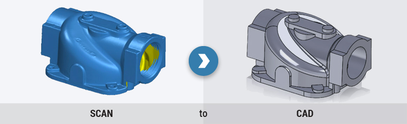
There are a number of reasons you want to go through the process of reverse engineering to convert scans to CAD.

First, programs to machine or 3D-print reproductions can read this data much more easily. It will produce a 3D-print with higher accuracy, smoother surface, as well as reduce printing time by creating efficient tool paths.

Secondly, if you would like to add any features with dimensional accuracy (example: I’d like to add another hole an inch away from the center of the part), only CAD data would be able to accomplish this task easily.

In conclusion, there are always options to capture the geometry of an item, and we are happy to help advise you the best tools to meet your specific needs.